Overview
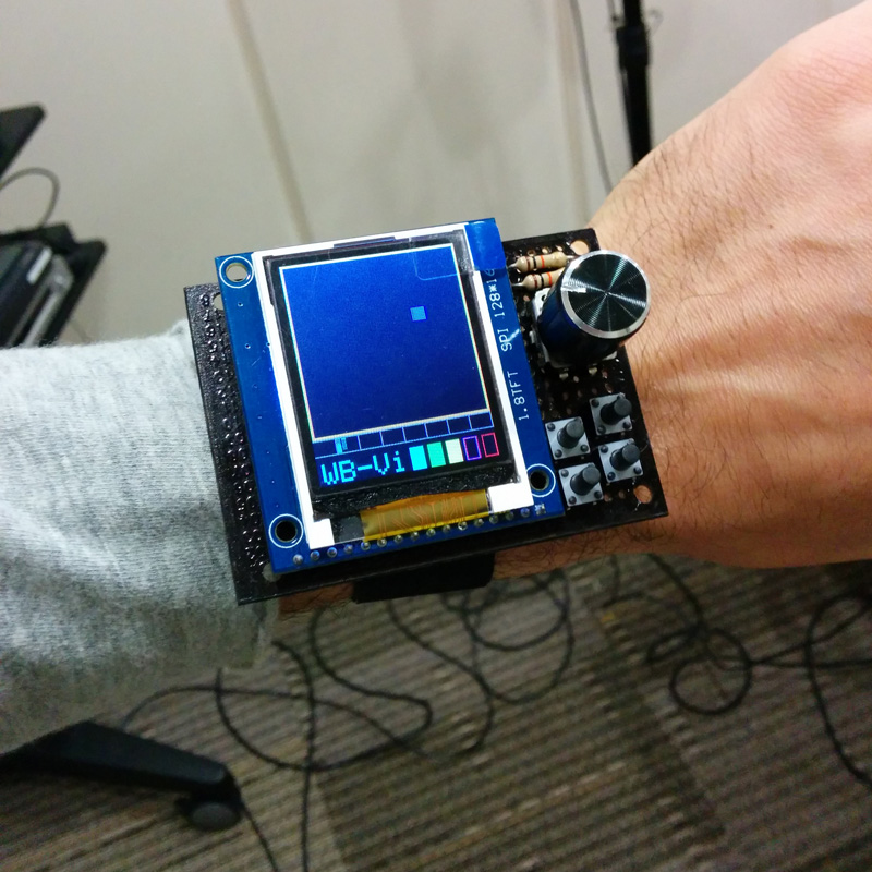
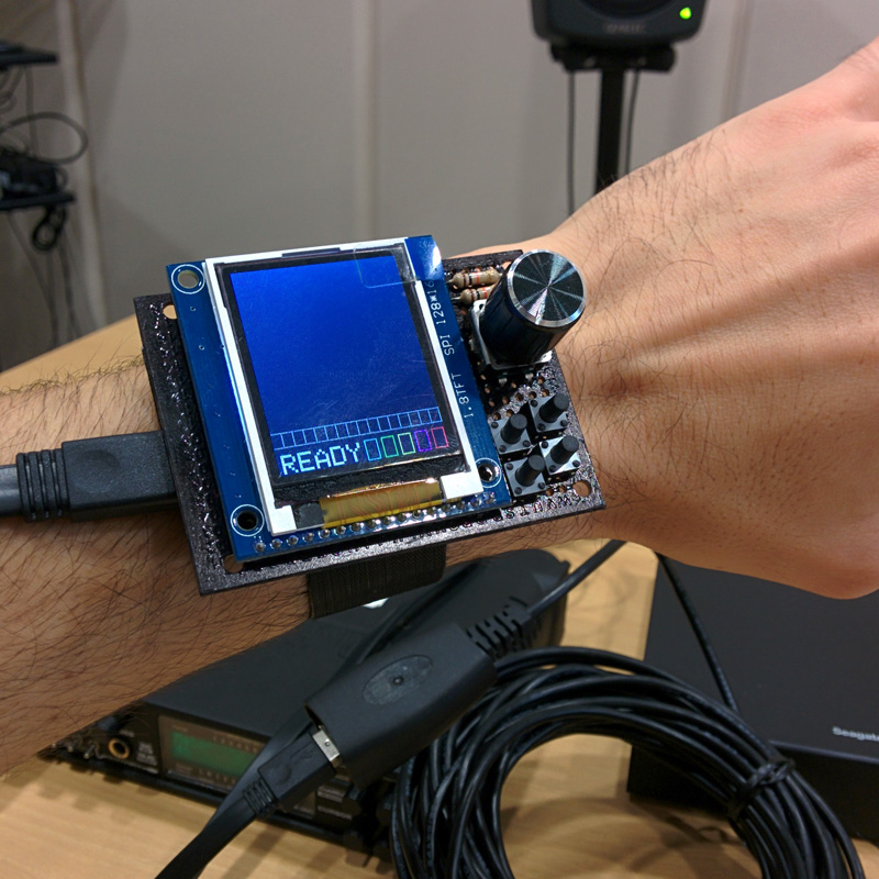
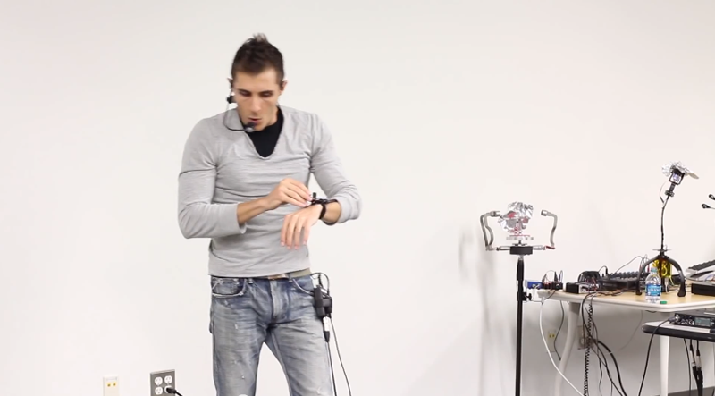
Laptops are widely used in computer music performances. They are present almost on every stage and performers use these machines for a broad variety of purposes. However laptops are general purpose devices and definitely not interfaces for digital musical instruments. Their use often requires a total visual engagement for entering commands or for the visual feedback. This can be annoying for some performers, misleading and unappealing for the audience. With the exception of live coding performances, the laptop represents a barrier which blocks listeners from establishing a relationship between the player’s gesture and the sonic result, so that some people may comment “is he just checking his email?”. The wrist worn interface provides to performers a minimalistic and miniaturized alternative to laptop screen and keyboard to execute key tasks, and display core information. The interface is wearable so that it doesn’t prevent the performer from freely moving on stage.
The wrist worn interface was initially designed for VCI4DMI system. In this context the performer uses exclusively the voice to control musical instruments, while few buttons are required to change preset and toggle some high level system functionality. On the other hand graphical representations of several status, a 3D space coordinate, and a temporal position are feedback that the performer periodically checks. Moreover in a second revision of the device a vibration motor has been introduced for providing the user with additional vibrotactile feedback. Therefore the wrist worn interface allowed removing the laptop from the stage, and provided freedom to the performer. It is connected to the laptop via USB, requiring a cable running up the arm inside the sleeve. The wired connection is not an issue since it runs towards the laptop together with the head worn microphone audio cable.
Design, Implementation and Assembling
The wrist worn interface features:
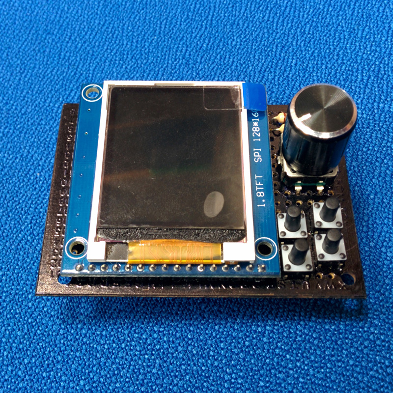
- Teensy 3.0 development board with a Freescale 32 bit ARM Cortex-M4 48 MHz CPU onboard
- 1.8″ TFT LCD with resolution 128×160 and SPI interface
- Four push buttons
- One rotary encoder with push button
- One vibration motor
The Teensy board was selected for its small size and for two key advantages against Arduino boards. Firstly it provides a more powerful microcontroller, essential to minimize the delay in visualization of the data on SPI driven TFT LCD. Then the microcontroller includes a USB device/host/otg which can be easily configured via IDE to USB MIDI mode. This turns the board into a plug ‘n play USB MIDI device compatible with most operative system without requiring specific drivers. On Arduino board USB MIDI mode is possible only flashing with a programmer the external Atmega16U2 (available only on some big size boards as Uno and Mega 2560) with an USB-MIDI firmware, such as Hiduino. This replaces the default USB-to-serial firmware and doesn’t allow the programming via USB and the USB serial communication. Moreover the Teensyduino add on for the Arduino IDE provides high compatibility between Tennsy and Arduino IDE, Libraries and code.
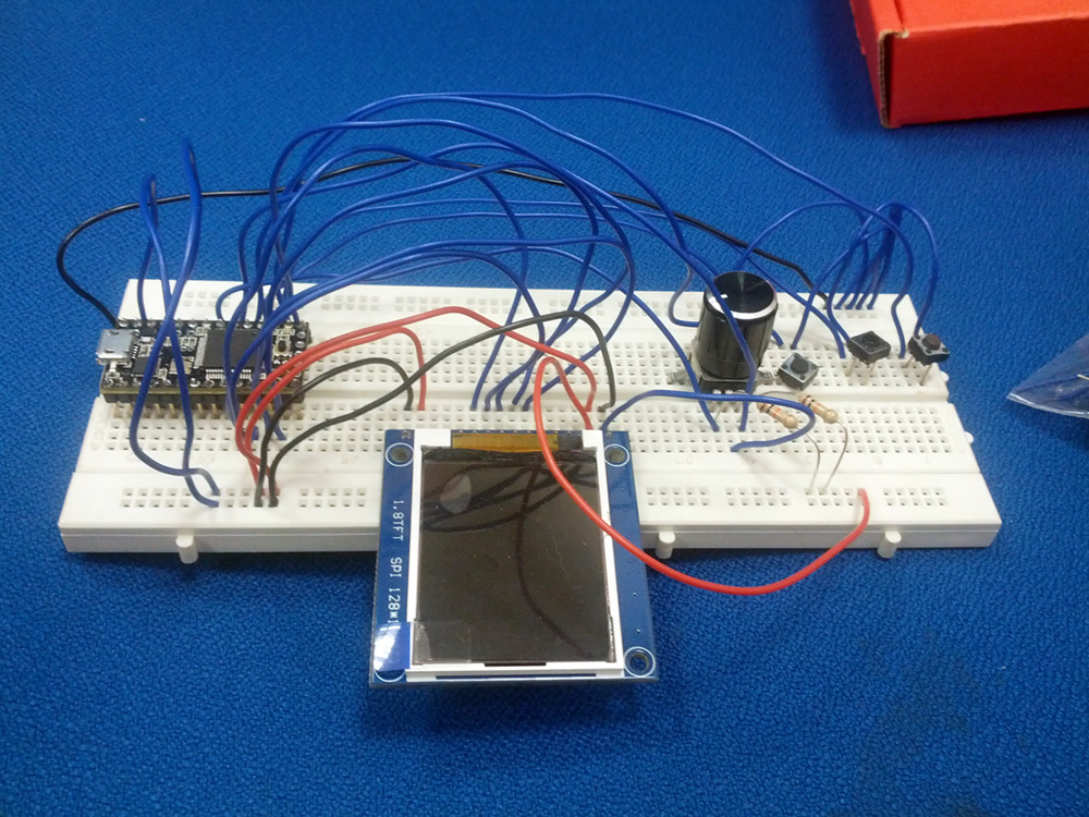
The 1.8″ TFT LCD used is compatible with the one from Adafruit but it is half of the price. However it present minor difference in the 18-bit word RGB color organization, requiring some macro redefinition from those in the ST7735 library, which can be used to control the LCD. Other Teensy libraries used in this project are the Encoder, Bounce, and MIDI, presenting similar or identical API to those for Arduino boards. The table below describes the connection between the Teensy boards and the other components of the system.
| Teensy pin AGND | TFT LCD GND pin 1 & LED- pin 16 | Teensy pin 14 | push button 1 |
| Teensy pin 3.3V | TFT LCD VCC pin 2 & LED+ pin 15 | Teensy pin 15 | push button 2 |
| Teensy pin 8 | TFT LCD reset pin 6 | Teensy pin 16 | push button 3 |
| Teensy pin 9 | TFT LCD A0 pin 7 | Teensy pin 17 | push button 4 |
| Teensy pin 10 | TFT LCD CS pin 10 | Teensy pin 18 | push button 5 (on encoder) |
| Teensy pin 11 | TFT LCD SDA pin 8 | Teensy pin 19 | encoder right (with 10K pull up) |
| Teensy pin 13 | TFT LCD SCK pin 9 | Teensy pin 20 | encoder left (with 10K pull up) |
| Teensy pin 21 | vibration motor | Teensy pin 22 | vibration motor |
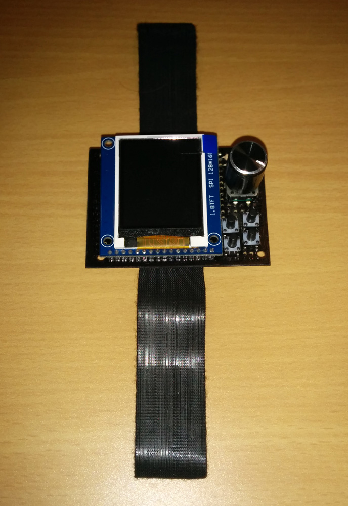
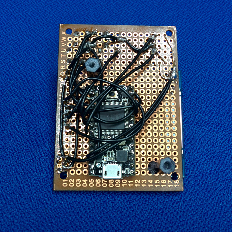
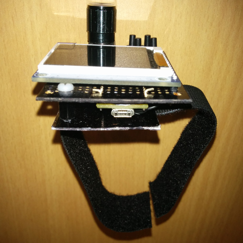
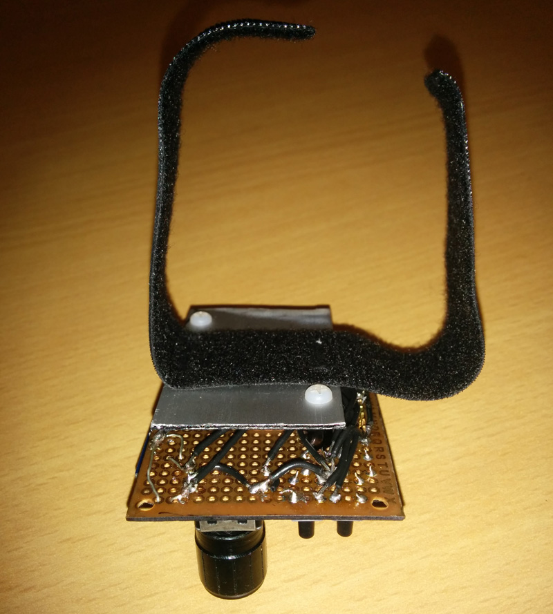
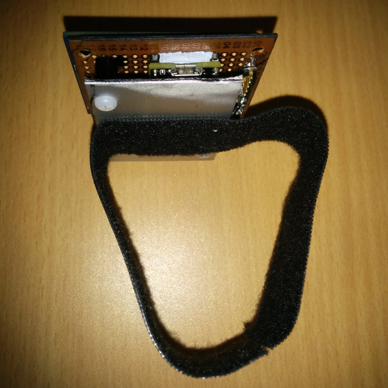
The other end of the five push buttons is connected to GND, as well as the central pin of the rotary encoder and the negative terminal of the vibration motor. The motor is connected to two Teensy pins in order to draw sufficient current to operate. The two vibration motor pins are toggled in simultaneously writing directly into the GPIOC_PDOR register to avoid fatal short-circuits within the Teensy micro. GND and 3.3V for the pull up resistors are provided by the Teensy board pins, which in turn is powered via USB. To operate at 3.3V the 1.8″ TFT LCD requires to close JP1 jumper on the back of the screen board. The components are soldered on a stripboard, positioning the screen, the buttons and the encoder on the top of the board, while the Teensy board and the hard wiring are on the other side. The bottom part of the board is covered with a metal plate, separated with two plastic element. The bottom plate protects the wiring and the teensy board, it hosts the vibration motor case, and it avoids short circuits that could happen if the pins touch the skin when worn. A velcro wristband is then installed on the cover plate.
For controlling the VCI4DMI system the program running on the Teensy microcontroller (source code) displays graphical elements on screen or vibrates according to a specific protocol based on MIDI note-on/off messages and MIDI control change messages. The buttons and the encoder send MIDI note-on messages to VCI4DMI Max/MSP patch, which in response command the update of come graphical elements. In the second part of the video below the 3D space coordinate (the 3rd dimension is mapped onto the red-to-blue gradient of the moving square), the time bar position and some status LED are driven from the Max/MSP patch not visible on screen.
- Wrist Worn Interface Prototyping
- Wrist Worn Interface Top
- Wrist Worn Interface Bottom
- Wrist Worn Interface Assembled
- Wrist Worn Interface USB port
- Wrist Worn Interface bottom protective plate
- Wrist Worn Interface bottom protective plate
- Wrist Worn Interface running the VCI4DMI program
- Wrist Worn Interface running the VCI4DMI program
- Georgia Tech Guthman 2014
