Overview
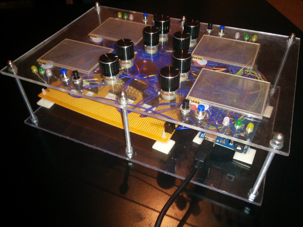
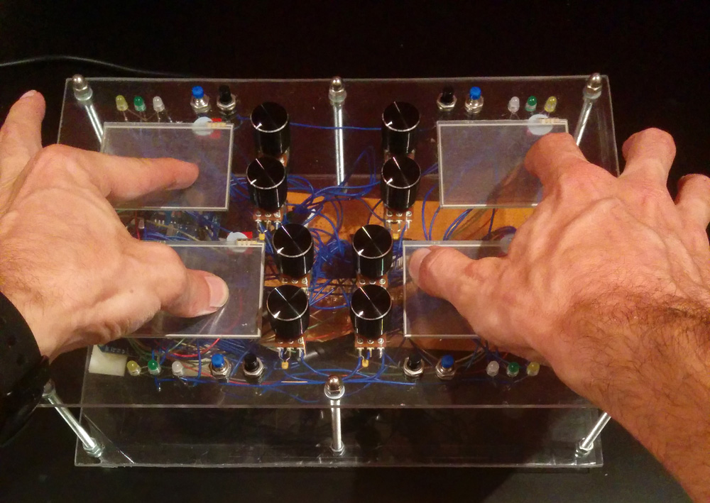
The QuadPad MIDI controller is a general purpose interface to drive hardware and software via MIDI. The main feature of the QuadPad is a set of four touchpads positioned in a way that they can be simultaneously operated. This would provide the concurrent control of 8 real-valued parameters or of a 8D space. The control of such a high dimensional space would be impossible or difficult to achieve, for physical constraints of the hands, using other interface elements such as knobs or faders. Moreover the QuadPad features eight rotary potentiometers, eight push button, eight LEDs and four tri-color LEDs installed on a plexiglas surface. The arrangement of the interface elements is modular to facilitate mapping of identical cluster of control on different sound sources. Each of the four module includes one touchpad, two rotary potentiometers, two buttons and three LEDs.
Implementation and Functionalities
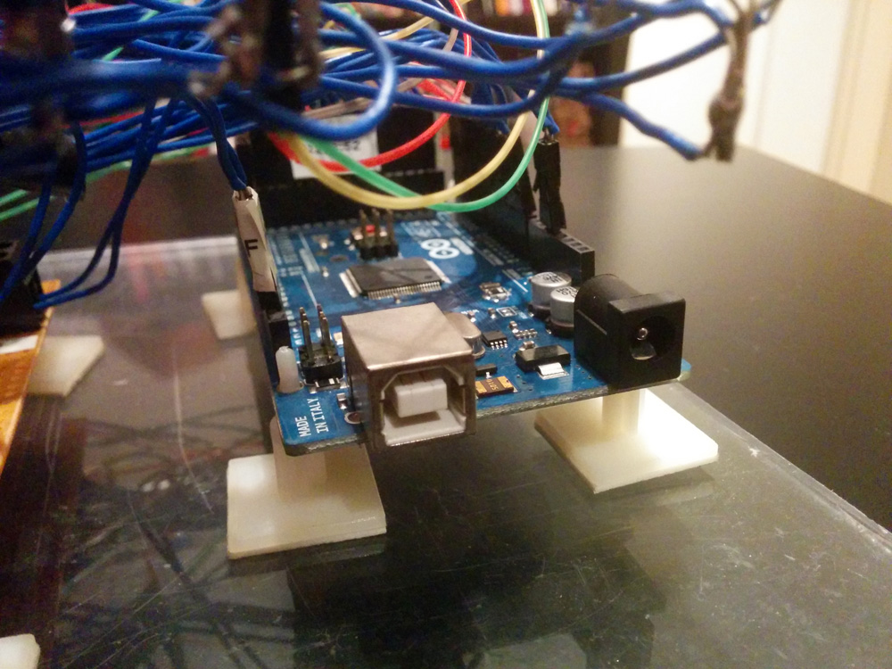
The core of the QuadPad is an Arduino Mega 2560 R3 featuring a high number of I/O pins, and in particular 16 10-bit analog input to interface the 4 touchpads and the eight rotary potentiometers. The Atmega16U2 on the Arduino board is flashed with the Hiduino firmware which turns the USB connection of the board from USB-Serial to USB-MIDI. This makes the QuadPad a plug ‘n play USB MIDI device compatible with most operative system without requiring specific drivers.
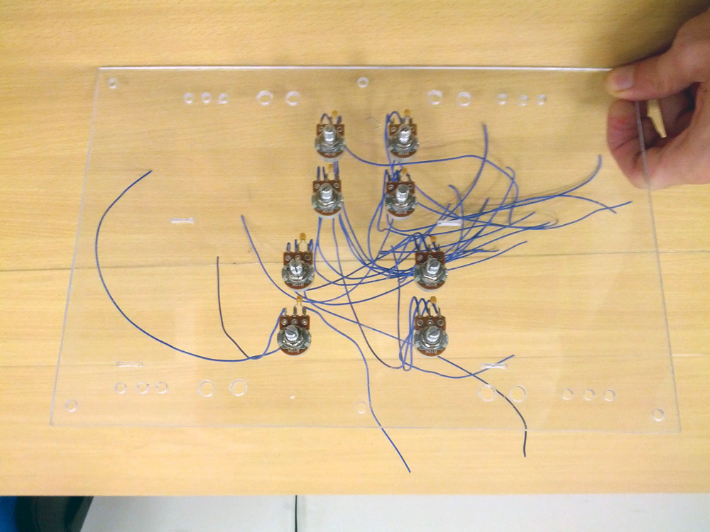
The 10KΩ linear potentiometers are connected to GND and AREF of the Mega 2560 board through pin 1 and 3, while the central pin 2 is connected to one of the 16 analog input of the Mega 2560. A 0.1μF ceramic capacitor is inserted between GND and the analog in (pin 1 and 2) in order to smooth the response (it works as a low-pass filter). The 10-bit ADC value returned by the analogRead() function spans between 0 and 1024, which is converted to the 7-bit MIDI Control Change value using the map(val,0,1024,0,127) function or with a right shift >> 3. The QuadPad potentiometers require some tuning to achieve the max value of 127 (e.g. mapping input max value to 1021 instead of 1024). Finally to avoid the QuadPad from continuously sending MIDI CC messages not due to human activity but due to noisy voltage changes, the analogRead() value is further smoothed taking the average of the last 5 readings, as described in this tutorial. This removes any spurious CC messages and doesn’t introduce a noticeable latency in the interface response.
The 4-wire analog resistive touch screen used are originally designed for the Nintendo DS. The X and Y positions are acquired separately reading a tension value from an analog input. The AREF, GND and variable resistor pin configurations are different for reading X and Y values. Thus it is necessary to continuously change the pin configuration. However only two analog input pins are necessary (these can be set also to digital out), the other two wires can be connected to the abundant Mega 2560 digital I/O pins, and changing their state between HIGH, LOW and INPUT_PULLUP. The connections, configuration and basic Arduino code are explained in this tutorial. Note that other tutorials include a 10KΩ pull-down resistor on the 4 wires, which are not necessary with these settings. Each touchpad drives two MIDI CC of the QuadPad and as explained above the 10-bit analog read value has to be mapped to the 0-127 range, requiring manual tuning on each touchpad to entirely cover the 7-bit ranges. When the touchpad is released the QuadPad can be configured (at startup) to hold the last MIDI CC or reset these to a specific user-defined value.
The positive of each LED is connected to the 5V provided by the Mega 2560 board and the negative is connected to a digital I/O pin via a 220Ω resistor. The tri-color LED is essentially one red and one green LEDs packaged together, so that when both are active the light seems yellow. Each tricolor LED has a common positive, connected to 5V and two negative, connected to separates digital I/O of the Mega 2560 through 220Ω resistors. The digital I/Os are set to output and the LED status is toggled changing the pin logical output voltage value using the digitalWrite() function (HIGH=off, LOW=on). Individual LED status is activated sending to the QuadPad specific Note On/Off messages.
The eight push buttons are connected to 5V on one pin, while the other is connected to a digital I/O pin set to input and GND through 10KHΩ resistor. The value is acquired using the Arduino Bounce library functions for that de-bouncing the digital inputs in software. Push button send individual Note On/Off messages.
The QuadPad is powered via USB. The 16 equivalent LEDs draw up to 352mA (approximately 22mA each one), which is below the 500mA typical USB max current by a sufficient margin to power the ATmega2560 microcontroller. The QuadPad has been used with different mappings in applications such as the dynamic spatial control of four independent sound sources, or in sound synthesis high dimensional timbre manipulation.
-

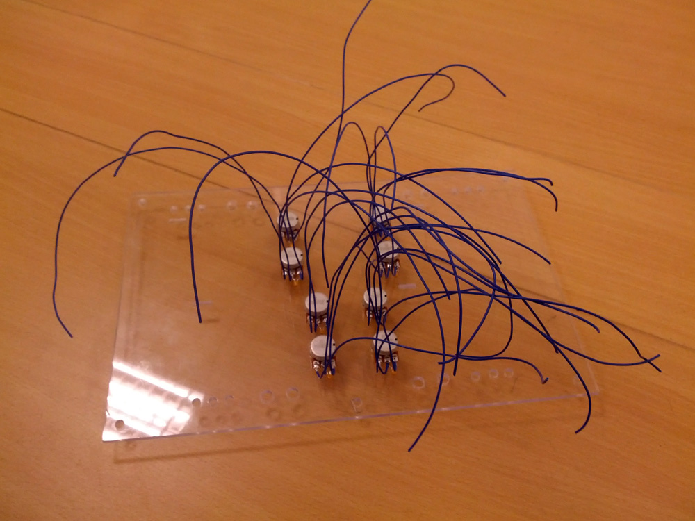
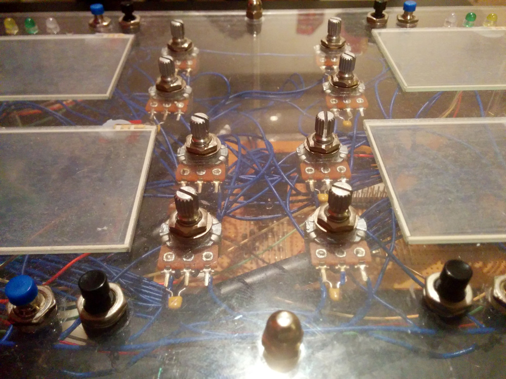
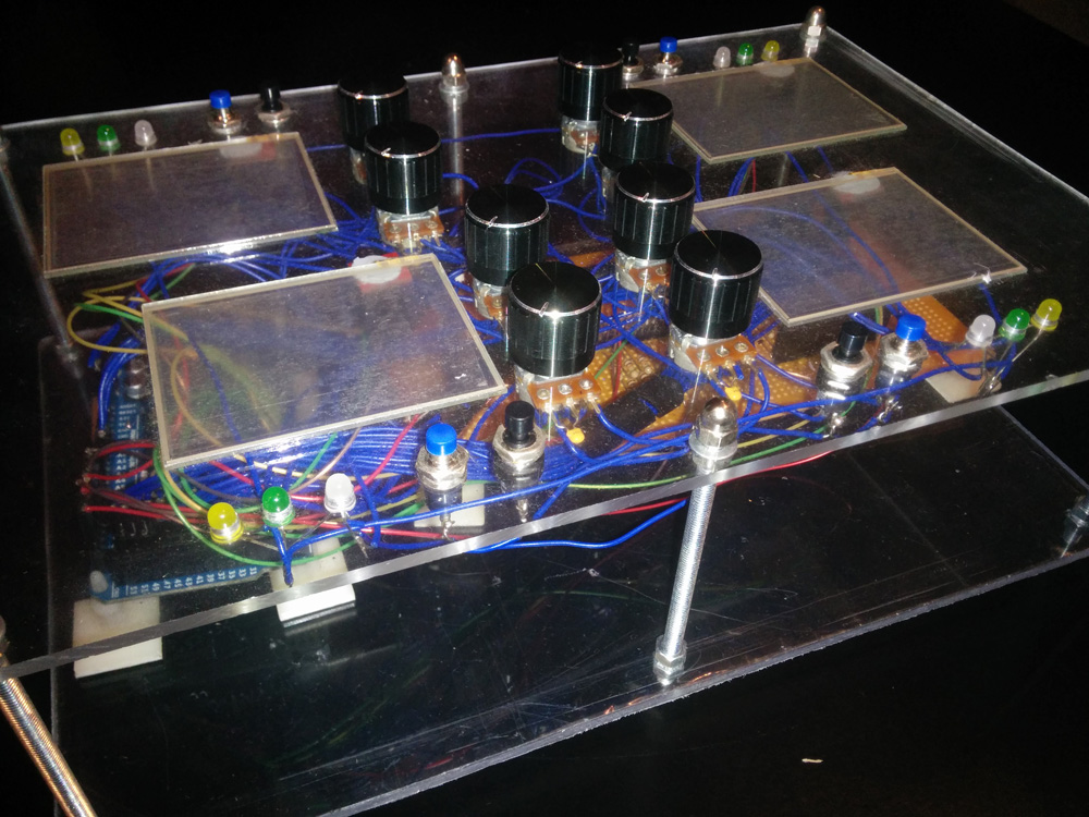
- QuadPad assembling
-
- QuadPad assembling
-
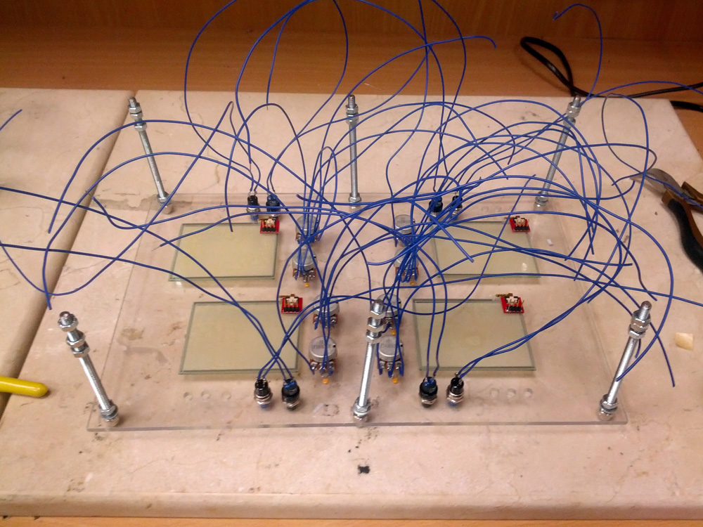
- QuadPad assembling
-
- QuadPad assembling
-
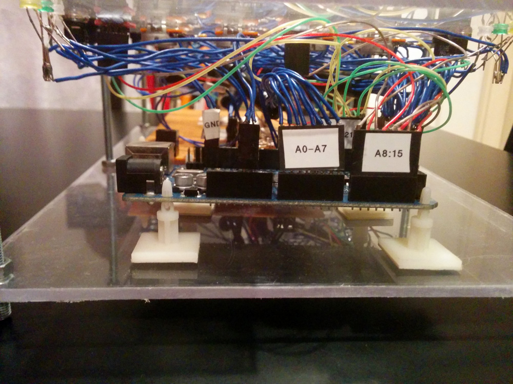
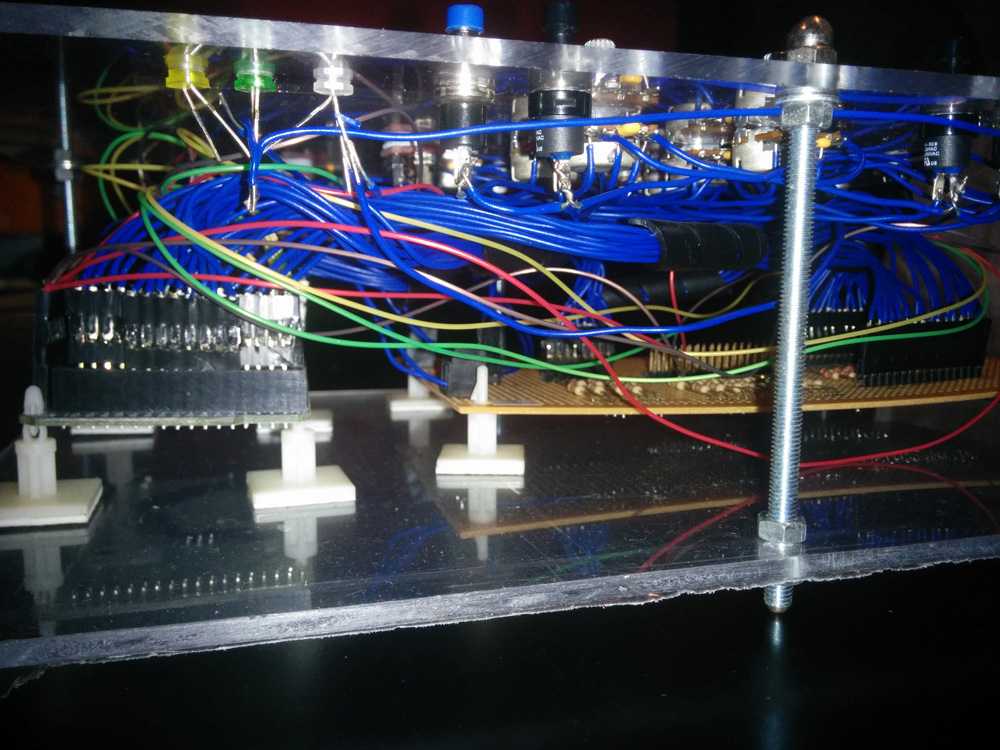
- QuadPad internal wiring jungle
-
- QuadPad internal wiring jungle
-
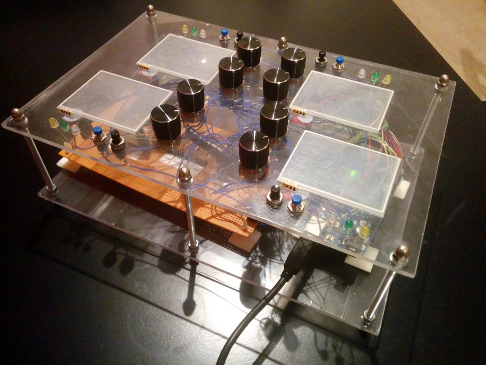
- QuadPad Arduino Mega 2560
-
- QuadPad assembling
-
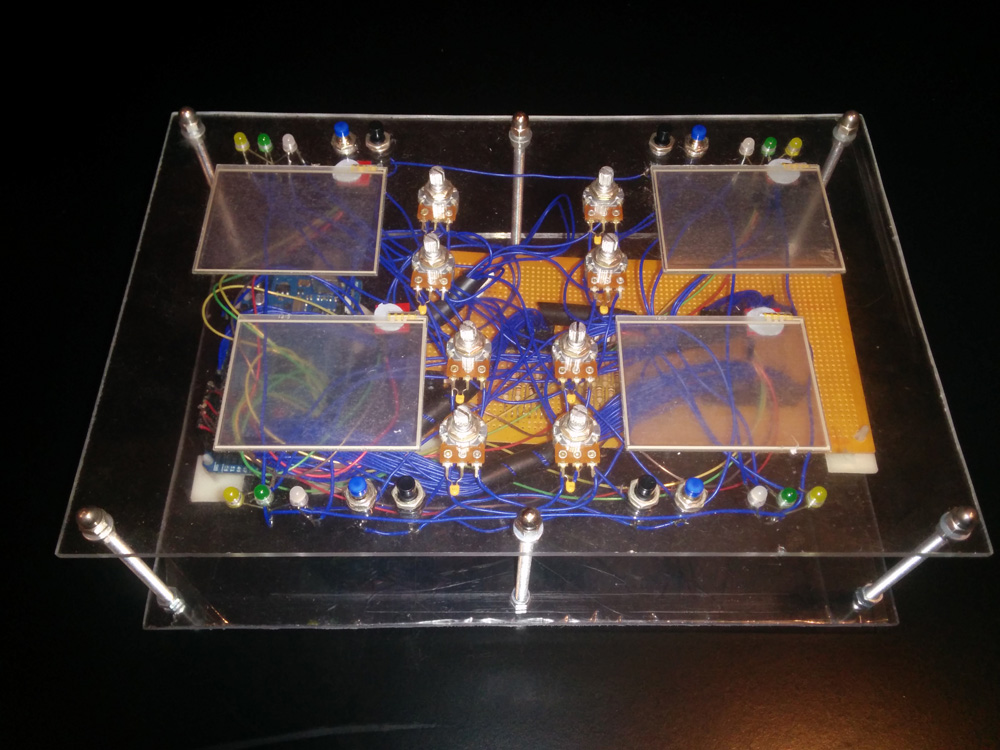
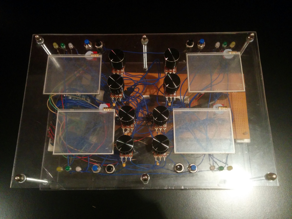
- QuadPad MIDI Controller
-
- QuadPad MIDI Controller
-
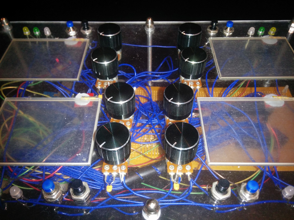
- QuadPad MIDI Controller
-
- QuadPad MIDI Controller
-
- QuadPad MIDI Controller
-
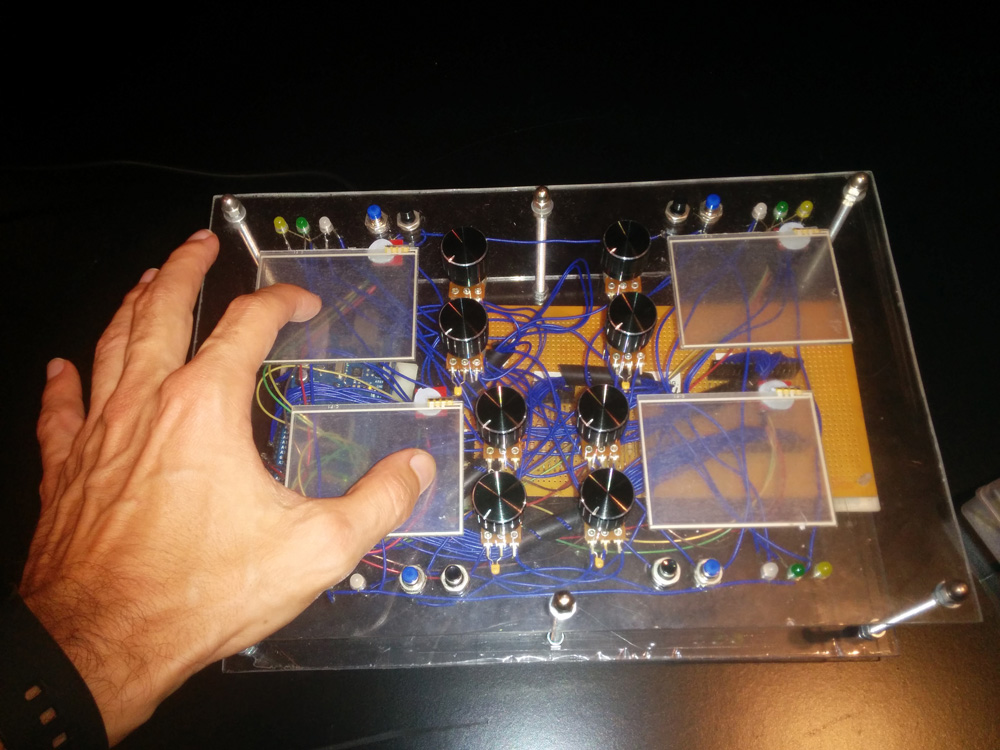
- QuadPad 4D control with 1 hand
-

- QuadPad 8D control with 2 hand